Harnessing Laser Technology for Precise Flat Surface Scanning
In the world of manufacturing, where surface quality is critical, the ability to detect defects quickly and accurately is invaluable. One of the most effective methods for this is laser line scanning. But how does it actually work?
In this post, we’ll take a closer look at how to project a laser line and how to observe it to spot even the tiniest surface irregularities. We’ll also explain what those irregularities mean — and what information the height of the laser line’s deflection can reveal.
How to Position the Camera and Laser to Detect Surface Defects Effectively?
Imagine pointing a laser line onto an uneven surface while standing just behind it, observing from the same angle at which the light hits. What would you see? Most likely, a perfectly straight line — as if the surface were completely smooth.
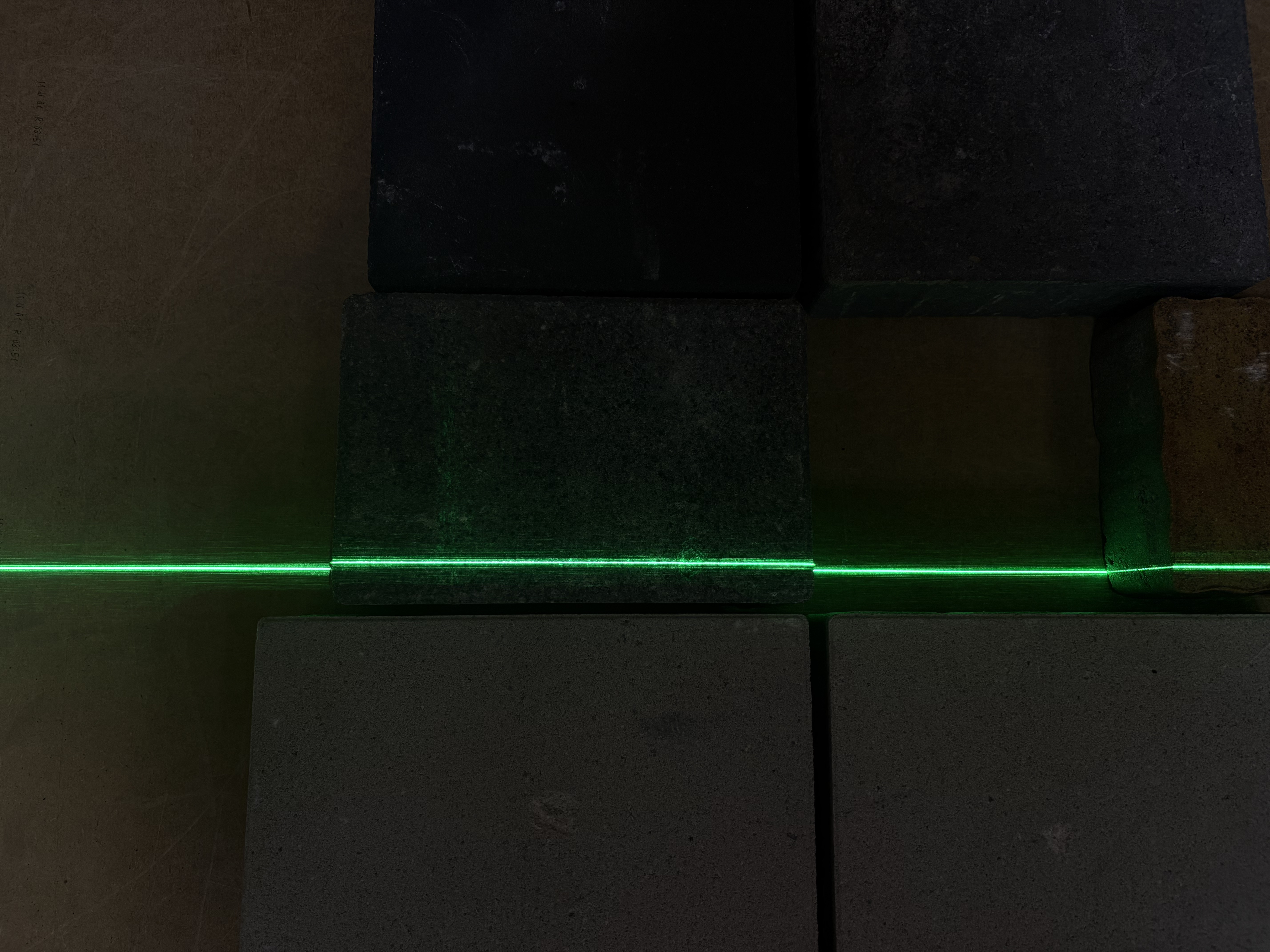
Photo 1 shows exactly this scenario — the laser line is seen from the same angle as the light hits the surface. The photo was taken with a low exposure setting, which darkens the background and makes the laser line stand out clearly. In automated inspection systems, such low exposure levels are often used deliberately, so that the camera captures only the laser line and nothing else.
To actually see how the laser line bends across irregular shapes, however, you need to change your viewing position. In other words, there must be an angle between the observer (camera) and the light source (laser).
There are three main configuration setups for this:
- Laser angled, camera perpendicular. This is the most intuitive setup — the laser shines at an angle onto the surface, and the camera looks straight down. It works well, but it has a few drawbacks (we’ll explore those in a future post).
- Laser perpendicular, camera angled. A less obvious approach, but often the most effective. This is the configuration we use in our advanced surface inspection systems — more on this in upcoming articles.
- Both laser and camera tilted relative to each other. This hybrid setup also has its advantages, though we use it less frequently for now.
What Does a Bent Laser Line Say About the Surface?
The way the laser line shifts in a setup where the laser shines perpendicularly to the surface and the camera observes it at an angle is crucial for detecting defects. Photo 2 shows this effect in action:

On the right side of the block, you can clearly see the laser line bending slightly downward compared to the rest of the line. What does that mean?
It indicates a depression on the surface — in other words, a potential hole or defect. Detecting these kinds of anomalies automatically allows production systems to spot quality issues instantly, without manual inspection.
How Can You Measure the Depth of a Defect Based on the Laser Line Deviation?
Now that we know how to position the components to observe the laser line bending over uneven surfaces, it’s time to answer the key question: what do these curvatures actually mean, and does their height carry any useful information?
As you can see in Photo 2, any distortion of the laser line is directly caused by a defect on the product’s surface. So, simply detecting a deformation in the line allows us to identify the presence of a defect.
But there’s more — the height of the laser line’s deviation over the defect also tells us how deep that defect is. To calculate the depth, you need to know the angle between the laser and the camera. With that information, and by measuring the amount of deviation, the defect depth can be computed using basic trigonometric relationships.
The easiest setup for this is a 45-degree angle between the components. In that configuration, the geometry forms a right triangle with 45°, 45°, and 90° angles — which means the height of the laser’s deflection equals the actual depth of the defect.
Wrapping Up
That’s it for the fundamentals of laser line scanning.
We hope this post helped you see how a simple change in perspective — combined with a bit of trigonometry — can turn an ordinary beam of light into a powerful tool for automated quality control.