How to detect defects on flat surfaces that cannot be seen with the naked eye?
In this article, we present an analysis of the problem of detection of surface defects, which are invisible under standard lighting conditions. We describe why simple vision systems fail and conduct an evaluation of three different lighting architectures. Finally, we explain why the linear laser scanning approach has proven to be the most effective and reliable solution.
Main Challenge: Defects Without Shadow
The primary problem in our quality control system was the detection of small holes on a flat surface. The key conditions that made this task extremely difficult were:
- Nature of defect: The holes had the same color and texture as the base material, which precluded a simple analysis of color or pattern.
- Ambient lighting: The production hall, with numerous roof and side skylights, was flooded with a powerful but extremely diffused light. This type of lighting is desirable for work safety, but for vision systems it is deadly — eliminates virtually all shadows.
Without shadows, the recesses become optically “flat” and indistinguishable from the rest of the surface.
The First Approach and Its Failure: A Standard CCTV Camera
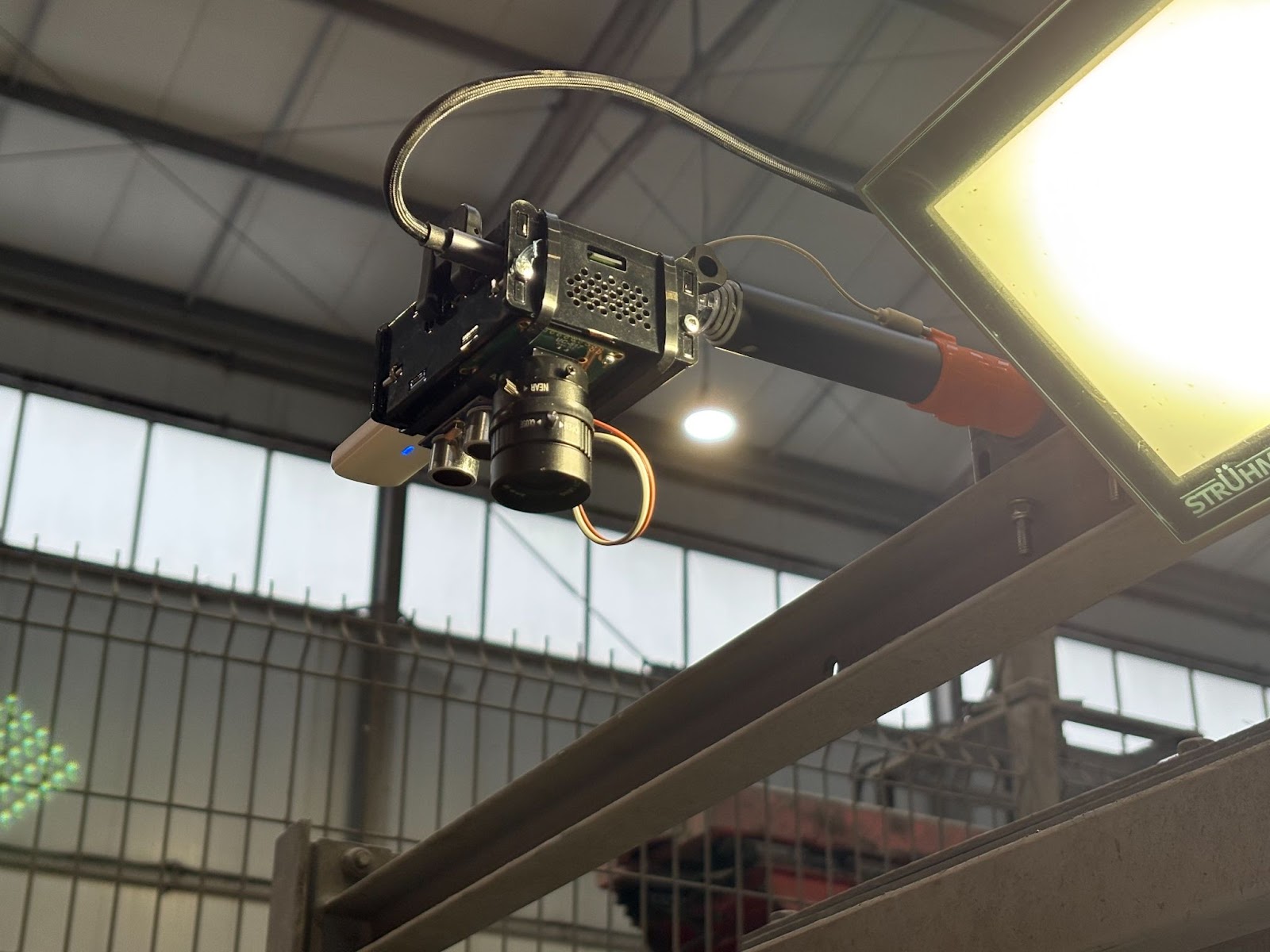
Our first hypothesis was to use a standard high-resolution industrial camera, aimed at the production line. Figure 1 shows how the camera is assembled together with the microcomputer above the production line.
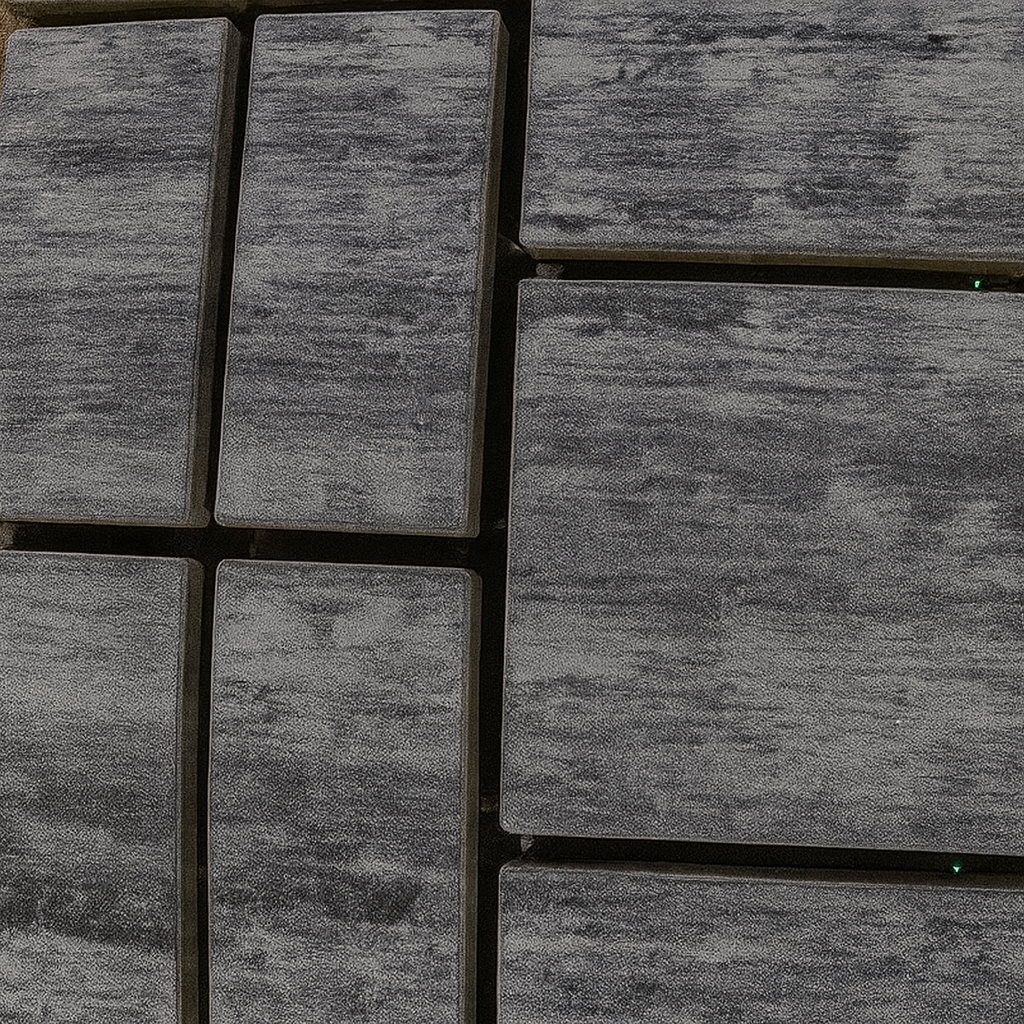
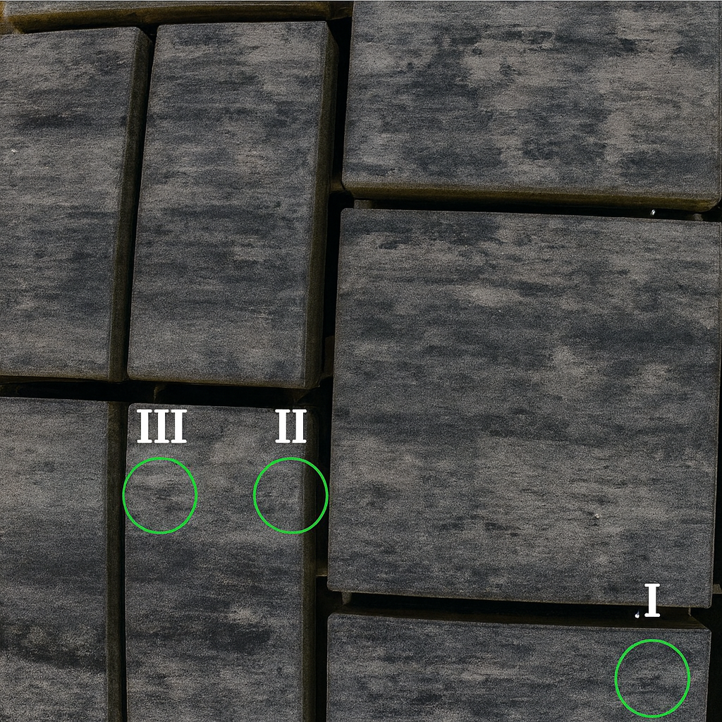
Result: Complete failure. The image captured by the camera showed no signs of defects. In Figure 2 there are cobblestones containing holes, it is impossible to find them because they are not visible. In Figure 3 we showed the location of the holes that were on the product, it was possible because physically we were in production at the time.
Failure Analysis: The problem was not in the resolution of the camera, but in the physics of the lighting. The absence of shadows in the image meant a lack of depth information. If the human eye does not see the defect under these conditions, the computer algorithm, based on the same input data, will not “see” it either. The conclusion was unequivocal: we need to take control of the lighting and actively generate shadows.
Evaluation of Alternative Lighting Architectures
We considered three competing lighting strategies, evaluating each for effectiveness, implementation complexity, and cost.
Approach #1: Linear Illuminator Set Parallel
- Concept: Use one long linear lamp, angled along the production line. This would allow the analysis of the entire product range in a single image, maximizing throughput.
- Problem: Unevenness of lighting. According to the law of inverse squares, the intensity of light drastically decreases with distance. Products close to the lamp would be overexposed and those in the center of the pallet would be underexposed. Adding a second lamp on the opposite side would smooth out the shadows. Moving the lamp a greater distance to unify the lighting would require so much space that the width of the machine would become unacceptable.
Verdict: Rejected. Theoretically fast, but practically unfeasible within reasonable physical limitations of the machine.
Approach #2: Linear Scanning Using LED Lamps
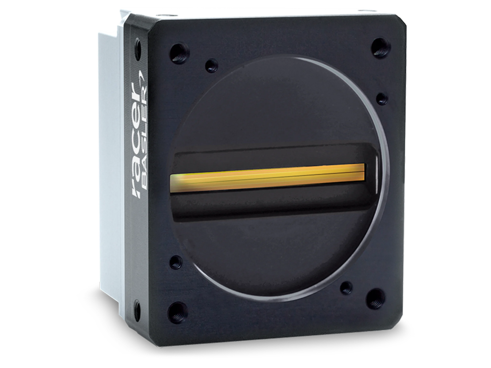
- Concept: Change the architecture from “whole palette at once” analysis to “line by line”. The linear lamp here is positioned perpendicular to the movement of the product and illuminates only a narrow strip. For image acquisition, it is used linear camera (for example, Basler racer with a matrix of 8192x1 px, shown in Figure 4). As the product moves, successive “lines” of the image are folded into a single, consistent, high-resolution scan.
- Advantages: Solves the problem of uniformity of lighting. We analyze only a narrow, well-lit fragment.
- Disadvantages:
- Mechanical Complexity: In order for the light to be focused, the lamp must be close to the product. The variable height of the products forces the use of an active lamp positioning system (e.g. on the servo), which introduces moving parts, increases the risk of failure and complicates the safety system.
- High Power Consumption: In order to “break through” the strong ambient light, the lamp must be very powerful, which translates into high energy consumption and heat generation.
Verdict: Technically feasible, but complicated and expensive to operate.
Approach #3: Laser Linear Scanning
- Concept: The architecture is identical to approach #2 (perpendicular scanning), but the light source instead of the LED lamp is linear laser.
- advantages:
- No moving parts: The focused laser beam allows you to place it at a great distance (1-2 meters) from the product. This completely eliminates the need for height adjustment and thus — servos, additional safety systems and complicated certification. The machine becomes simpler and more reliable.
- Extremely low power consumption: Lasers that generate a clear line, capable of overexposing ambient light, have a power consumption of less than 1W.
Verdict: Winner. It offers all the advantages of linear scanning while eliminating its main drawbacks — mechanical complexity and high power consumption.
Decision and Next Steps
We chose a laser-based approach because it offers the most reliable and cost-effective architecture to solve the problem. The elimination of moving parts was a key factor that directly translates into a lower total cost of the machine and its higher operational availability.
In the following parts of this series, we will delve into the implementation details:
- Selection of laser parameters: wavelength, power and beam shaping optics.
- Analysis of the signature that the laser line leaves on different types of defects.
- Image processing strategies and algorithm construction for automatic interpretation of scanner data.