Camera or Laser — What Should You Choose First, and Which Parameters Really Matter?
Building a Reliable Laser-Based Vision System: A True Engineering Challenge
Designing a reliable vision system based on laser technology—whether for 3D triangulation or surface profiling—is a classic engineering challenge. It’s not about simply buying parts from a catalog; it’s a system design exercise where every decision has a ripple effect.
The key issue is that the parameters of the camera and laser are tightly interdependent. A poor early choice (for example, an unsuitable camera sensor) can force costly and suboptimal compromises later on—like having to use a laser with dangerously high power or an uncommon wavelength.
So how do you handle this “chicken and egg” problem? Which should you choose first? Let’s explore the critical parameters and how they affect each other.
Key Component Parameters
Let’s start by defining the essential parameters for each component.
1. Camera
- Sensor size and type: Determines sensitivity and field of view.
- Shutter type (Global vs. Rolling): A fundamental choice. A global shutter is almost always required for inspecting moving objects to avoid distortion. Rolling shutters are cheaper but suited mainly for static scenes.
- Resolution: Pixel count (e.g., 1920×1080) defining image detail.
- Frame rate (FPS): Must be synchronized with the production line speed.
- Mono vs. Color: For laser inspection, monochrome cameras are almost always preferred—they lack the Bayer filter, making them far more light-sensitive, which is crucial for capturing faint laser lines.
- Interface: e.g., GigE (Ethernet) for long-distance stability or USB 3.x for high bandwidth at short distances.
- Built-in features: On-camera preprocessing or edge analytics can be valuable additions.
2. Optics (Lens)
- Focal length (e.g., 12mm, 25mm): Defines the field of view.
- Aperture range (F-stop, e.g., f/1.8–f/16): Controls light intake and affects depth of field.
- Maximum supported sensor size: The lens must cover the entire camera sensor (e.g., 1/1.8” or 2/3”).
- Distortion: A key factor in precision measurement, often expressed as a percentage.
3. Laser
- Power (e.g., 5mW, 100mW): Defines brightness.
- Wavelength (e.g., 520nm, 660nm): Determines color (if visible) and—most importantly—how well the sensor “sees” it.
- Lens type: For instance, generating a line, cross, or point grid.
- Lens divergence angle: Defines the projected line length at a given distance.
Sensor Sensitivity vs. Laser Wavelength
This is one of the most fundamental dependencies—and one of the most common sources of error.
In systems designed to detect laser line anomalies, that line must appear clear and high-contrast on the image.
You might think, “Just use a stronger laser.” That’s a mistake.
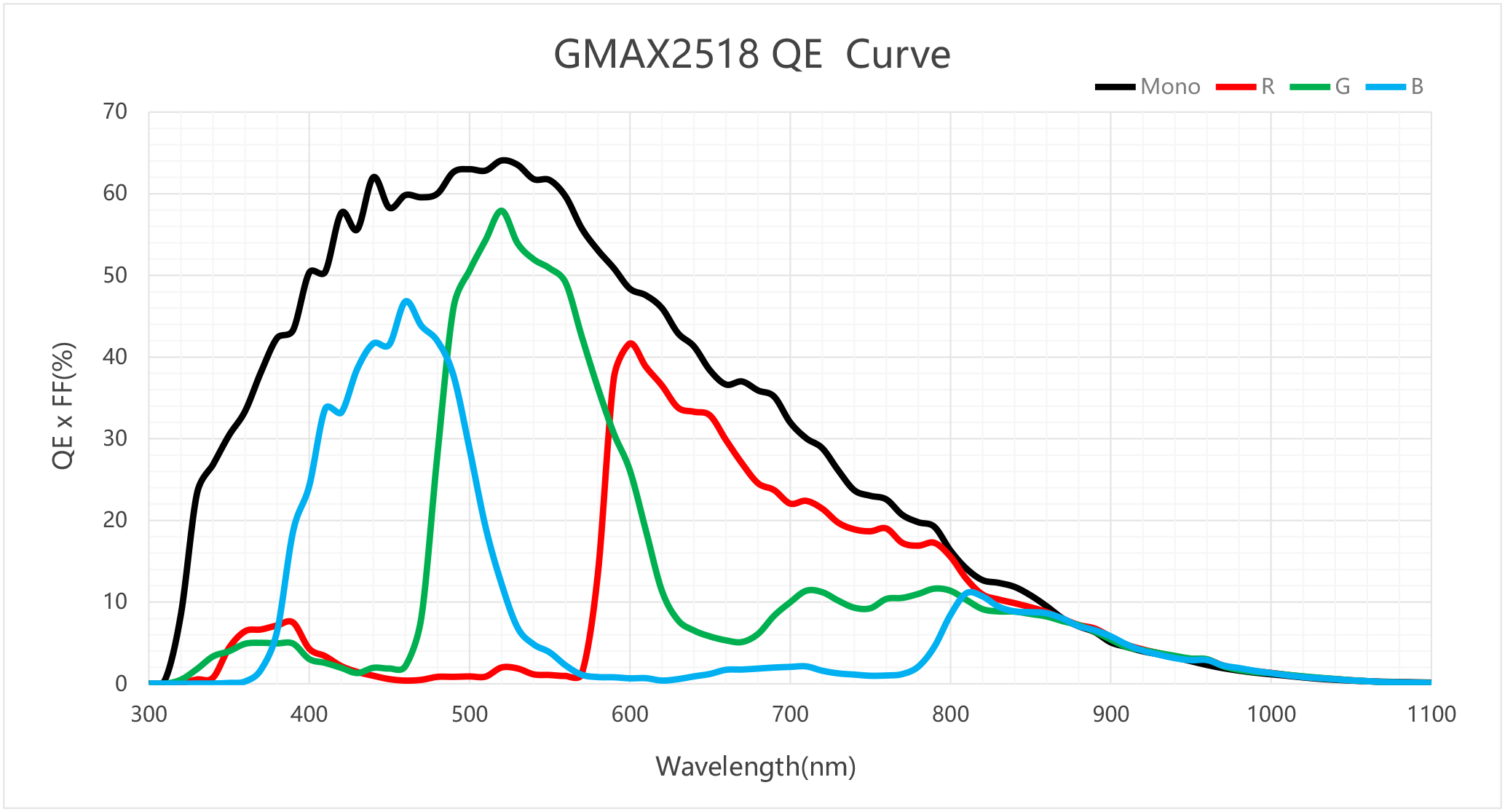
Each sensor has different spectral sensitivity, meaning its responsiveness varies with light wavelength. This is shown by the Quantum Efficiency (QE) curve.
For example, a popular mono sensor like the GMAX2518 peaks around 520 nm—the green region of the visible spectrum.
What does this mean in practice?
- Using a green laser (520 nm) allows the sensor to operate near peak efficiency, producing a bright image even at relatively low laser power.
- If you use a red laser (around 638 nm), sensor sensitivity drops noticeably. For this specific sensor, the brightness difference between green and red lasers can exceed 20 percentage points.
- Move further into the infrared range (e.g., 850 nm), and sensitivity plummets—the sensor becomes almost “blind.”
Conclusion:
If your laser power is limited (for example, due to operator safety regulations), you should choose a wavelength close to your sensor’s QE peak. Otherwise, you’ll struggle to extract a usable signal from the noise.
Aperture (F-stop) vs. Depth of Field
Another critical relationship lies in the lens aperture. The F-stop determines how much light enters the lens:
- Low F-stop (e.g., f/2.0): Wide aperture, lots of light. Great for bright laser lines and short exposures.
- High F-stop (e.g., f/8.0): Narrow aperture, much less light.
It might seem logical to always aim for the lowest F-stop to “catch” as much laser light as possible. Unfortunately, physics doesn’t offer free lunches.
A wide aperture (low F-stop) drastically reduces depth of field (DoF).
Why is that a problem?
Imagine inspecting boxes on a production line. If the depth of field is razor-thin (say, at f/2.0), even a 1 mm height variation or slight tilt will push the laser line out of focus—making it blurry and unreliable for computer vision algorithms.
Closing the aperture (e.g., to f/8.0) greatly increases DoF, keeping the laser line sharp even if the object moves slightly. But the trade-off is light loss—you’ll need either longer exposure times (often impossible on fast-moving lines) or a much stronger laser.
And so the balancing act begins again.
.jpg)
Iterative Design in Practice
As you can see, selecting these components is a tightly coupled process:
- Fast line → short exposure
- Short exposure → more light needed
- More light → stronger laser or lower F-stop
- Lower F-stop → shallower DoF
- To keep high DoF → higher F-stop → even stronger laser
- Laser power → limited by safety, budget, and sensor QE
It’s impossible to calculate the perfect setup purely on paper. The biggest unknown is always the object itself. How the laser line reflects—off glossy metal versus matte plastic—changes everything.
That’s why real-world system design often relies on empirical testing.
In one of our recent projects, we followed this process:
- Define constraints: We first set the field of view and required precision, which helped us select a camera (with suitable resolution and shutter type) and lens.
- Lab testing: We ordered a range of lasers with different powers and wavelengths for trials.
- Verification: We tested combinations on real material samples, tuning aperture (F-stop) and exposure time to find the optimal balance of laser brightness, focus depth, and measurement stability.
This approach allowed us to identify the laser that delivered the best contrast and consistency under realistic exposure conditions.
(A big thank-you to the team at Lambdawave (lambdawave.eu) for their expertise and generous support during the testing phase.)
In the following articles, we’ll dive deeper into component selection and parameter tuning.
Given the scope and importance of this topic, each major component will get its own dedicated post.