How to Choose a Camera for Line Scanning Flat Surfaces?
In computer vision systems — especially in production quality control — one brutal rule always applies: Garbage In, Garbage Out (GIGO). You may have the most sophisticated AI model, but if you feed it weak, noisy, or distorted data, the results will be at best unpredictable and at worst — expensive.
The camera is the “eye” of your system. In line-scan applications, where the product moves at high speed, choosing the right camera is not just another procurement task. It’s a fundamental design decision that directly defines the upper limit of accuracy and reliability for the entire system. A wrong choice at this stage is almost impossible to compensate for in software.
In the previous post we defined a general list of camera parameters. Today, we’ll analyze the key ones in the context of scanning flat surfaces, focusing on the technical trade-offs you’ll face when making this choice.
Sensor Type and Size
The first and most critical decision regarding the sensor is the type of shutter. There are two basic groups: rolling shutter and global shutter.
For systems scanning moving objects, this choice is absolutely critical.
- Rolling Shutter: Reads the image line by line, from top to bottom. If an object moves faster than the sensor can be read out, the resulting image will be distorted (the “jello effect”).
- Global Shutter: Exposes and reads all pixels simultaneously. It freezes motion and provides a geometrically correct image.
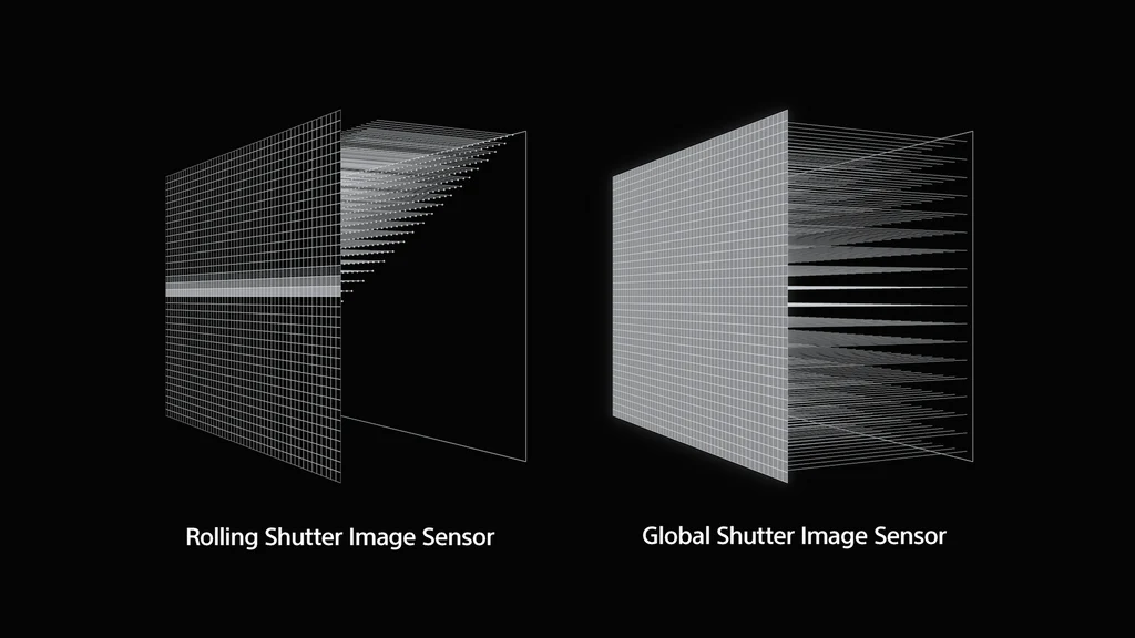
This difference becomes dramatically visible when capturing objects in motion. A rolling-shutter sensor introduces artifacts that make precise measurements impossible and significantly complicate defect classification.
.jpg)
Conclusion is simple:
Rule #1 Whenever you are capturing moving objects (e.g., a product on a production line), using a global-shutter sensor is absolutely essential to ensure the image reflects reality accurately.
Another key sensor parameter is its physical size (e.g., 1/2”, 2/3”, 1”). A larger sensor — and therefore larger pixels — provides a better signal-to-noise ratio (SNR) and higher sensitivity. With short exposure times required by fast-moving lines, the ability to gather as much light as possible is crucial for a clean image.
Of course, a larger sensor means a higher cost (both for the camera and the required optics). In our experience, for demanding industrial applications, 1-inch sensors or larger deliver noticeably better image quality and are worth considering as a starting point.
Resolution
Resolution directly determines the level of detail. It must be chosen based on the size of the smallest defect (or feature) the system needs to detect reliably.
In engineering practice, we use this proven rule:
Rule #2 The smallest feature of interest should be represented by at least 3 to 5 pixels.
For example: if the scanning width is 1200 mm and the smallest defect you want to detect is 1 mm, your camera should have a horizontal resolution between:
- 3600 px (1200 / 1 × 3)
- 6000 px (1200 / 1 × 5)
Higher resolution allows lower mean absolute error (MAE) and better detail reproduction, but with an important trade-off: more data to process. This increases compute requirements and can slow down the system.
“More” isn’t always “better” — the key is balancing precision and computational efficiency.
Camera Speed (FPS) vs. Line Speed
The camera’s frame rate (FPS) must be synchronized with the production line. The critical parameter is the maximum line speed of the product.
Production lines often vary in speed, so the vision system must be designed for the fastest possible scenario.
A key technique in line-scan applications is Region of Interest (ROI). Camera specifications list maximum FPS for full-sensor readout — but for scanning flat surfaces, you rarely need the full height (e.g., 3000×3000 px). You can configure the camera to read a narrow window, e.g., 3000×400 px.
This dramatically reduces the amount of data and can increase the effective FPS by several times. It’s a standard optimization in this class of applications.
Many manufacturers (e.g., Basler) provide calculators to precisely compute achievable FPS for a given ROI: Basler Frame Rate Calculator.
Color or Monochrome Camera?
This choice is easier than it seems. In industrial applications, the default and preferred option should nearly always be a monochrome (mono) camera.
Why?
- Less data: An 8-bit mono frame produces 3× less data than an RGB image (24-bit). This reduces computational load and interface bandwidth requirements.
- Higher sensitivity and sharpness: Color sensors use a Bayer filter, where each pixel captures only one color (R, G, or B). The other two channels are interpolated (demosaiced), slightly blurring the image. A mono pixel captures the full spectrum, giving inherently higher sensitivity and sharper detail — crucial with short exposures.
A color camera should be chosen only when color itself is a key differentiating feature of the defect (e.g., print color inspection, detecting chemical discoloration).
Communication Interface
In production environments, the interface is not just about bandwidth — reliability and noise immunity are even more important.
- USB: Easy to implement, popular in edge AI units (e.g., NVIDIA Jetson). Unfortunately, standard USB cables are susceptible to electromagnetic interference (EMI), especially beyond 3 meters. Nearby motors or inverters can cause frame drops or communication errors.
- Ethernet: A far more robust, industry-standard choice. Supports long (up to 100 m), shielded cables. A key advantage is PoE (Power over Ethernet), which powers the camera and transfers data through one cable, greatly simplifying installation.
If your compute unit has only one Ethernet port (e.g., used for factory network access), it’s often better to add a dedicated network card for the camera rather than rely on potentially unstable USB operation.
Built-In Camera Features
Modern industrial cameras are small computers. It’s worth checking what functions they support before the image reaches the host machine.
- ROI (Region of Interest): Critical for increasing FPS.
- Binning: Merging neighboring pixels (e.g., 2×2) into a “super-pixel.” Reduces resolution but significantly increases light sensitivity (SNR) and readout speed. Useful in low-light conditions.
- Trigger control: Ability to be precisely triggered by an external signal (e.g., a photocell detecting the start of a product) and to control lighting (e.g., a strobe). Essential for synchronization with the production line.
- Frame compression: For high data throughput, lossless compression inside the camera can reduce bandwidth usage (e.g., over Ethernet), with decompression done just before analysis. This is especially important when using multiple cameras.
These features cannot be added later in software. Understanding your problem and defining these requirements before selecting hardware is crucial for the project’s success.