How to build a testing-environment for a linear surface scanning?
In our three previous posts, we covered the selection of key components for a vision system used in linear surface scanning: camera, lens, and linear laser. Now it's time to assemble them into a functional system which means, to build a testing environment where these elements can be realistically put to test.
Linear scanning requires the product under inspection to move past the measurement components - ideally at a constant speed, without stopping (there are also solutions that allow for stopping mid-process, but that's a separate topic). The test stand must therefore simulate a production line. In practice, this boils down to two elements: a motion system and a support structure for the measurement components.
Motion System - Simulating a Production Line
The first element we need to work on is the motion system that simulates a production line. We place a pallet on it, and products on the pallet. In our case, the products are paving stones, sourced for testing from local manufacturers.
We have Michał on board, who is responsible for automation and construction. A sketch of the system was created in a few minutes (Photo 1), and it was immediately clear which direction we were heading.
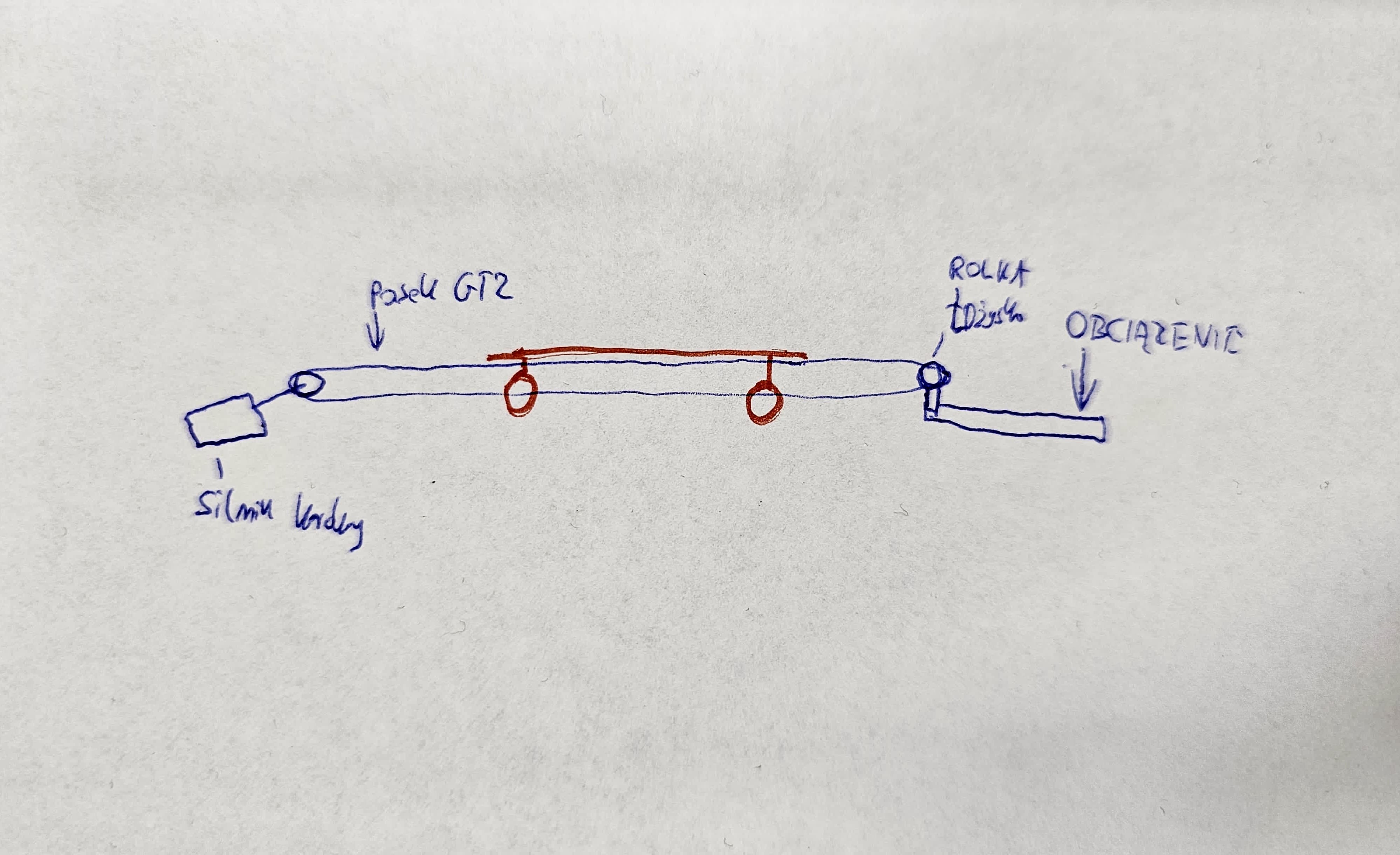
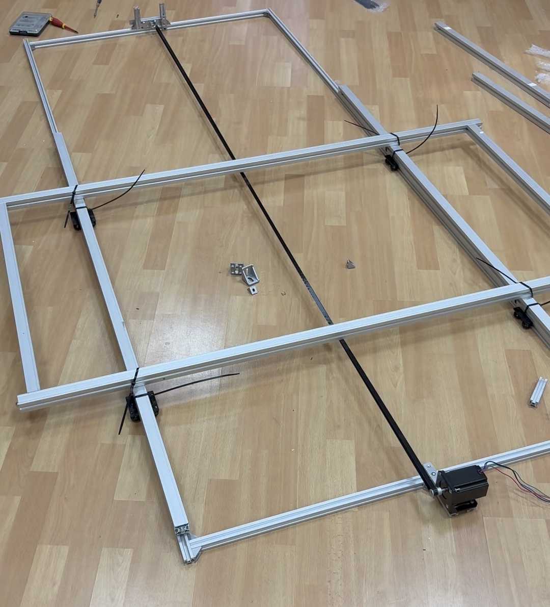
The operating principle is simple. The basic frame consists of 20×20 aluminum profiles. A stepper motoris mounted at one end, and a GT2 belt tensionerat the other. Rollers are placed on the profiles, and additional profiles, responsible for the pallet's load-bearing capacity, are attached to them. These roller-mounted profiles are coupled with the GT2 belt, allowing the motor — via the belt — to set the pallet in motion. The complex drive system is shown in Photo 2.
Support structure for the camera and line laser
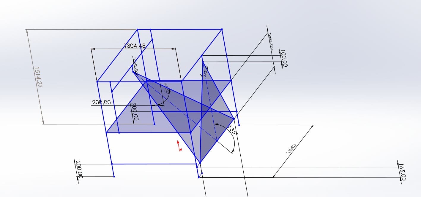
With the drive system in place, we needed a structure to mount the previously selected components — the camera with its lens and the line laser. This is where Michał stepped in again. Considering all variables (laser lens divergence angle, lens field of view, pallet width, possible product heights), he prepared a CAD design (Photo 3) and sent it to a familiar profile supplier.
Assembled test stand and control automation
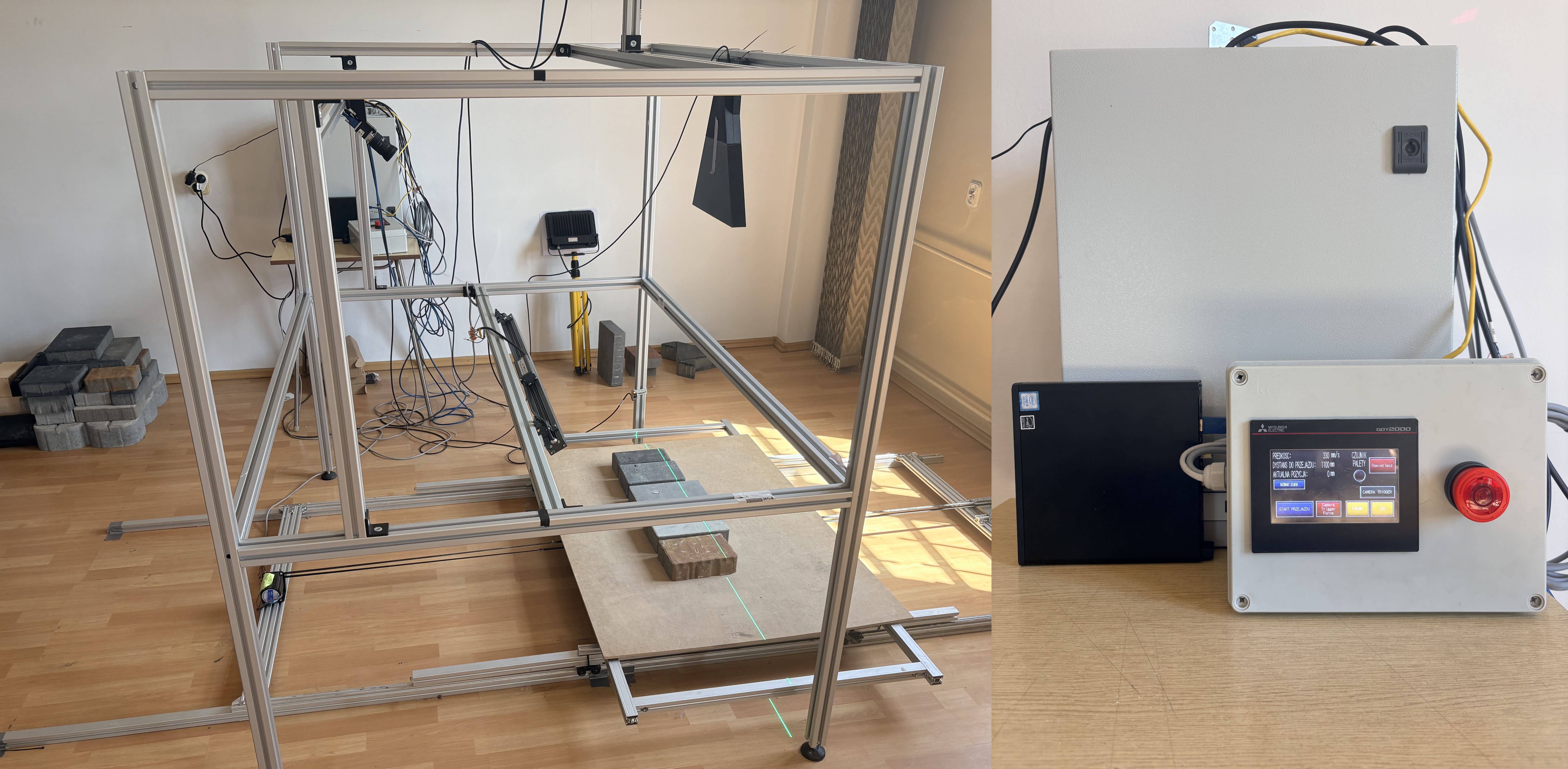
After the profiles were delivered, we assembled the entire setup (Photo 4). We now have a structure with measurement components, a drive system beneath it, and control automation next to it, managing the system's: speed, travel distance, acceleration, and braking. The latter two parameters are particularly important because the pallet carries significant weight — something that must be considered when dealing with paving stones.
Why build your own test stand?
Having such a stand is invaluable. Above all, it allows you to prepare and test algorithms even before production deployment — in any configuration, with any product arrangement, and without the pressure of the client's production line.
However, this doesn't replace one thing: a pilot installation at a potential client's site. In the next post, I'll show why such a pilot is a true game-changer — and what can't be detected in a laboratory, no matter how well equipped it is.