How to choose a laser and its optics for linear scanning of flat surfaces
In previous posts we discussed two of the three key components of a vision system for surface inspection — the camera and optics. Today, it's time for the third, equally important element: the light source, specifically a line laser. As before, we will go through the most important parameters one by one and explain what they really mean in design practice.
Lens type and its fan angle
The first decision concerns how the laser should project light onto the inspected surface. There are many possibilities: a single dot, a line, a cross, a grid of dots — it all depends on the lens used.
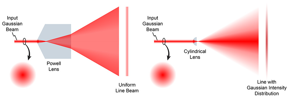
For surface scanning systems, we need a line laser, which splits a single beam into a line. At this point, it's worth considering the so-called Powell lens. It generates a line with uniform thickness and even intensity across its entire width. The difference is clearly visible in Photo 1: on the left, a line with a Powell lens; on the right, without it. Without a Powell lens, the center of the line is noticeably thicker and brighter, while the edges are thinner and dimmer.
In our experience, using a Powell lens is one of those choices where it's not worth cutting corners — it directly translates to the quality of subsequent measurements.
The second parameter of the lens is the divergence angle. It works similarly to the focal length in a camera lens — it defines how far we need to move the laser away from the illuminated object to cover it entirely with light. In practice, a proven starting point is a 60° lens — a good compromise between working distance and line quality. If mounting space is severely limited, you might consider 90°, but you have to accept that the line quality will be significantly worse.
Wavelength
Wavelength is nothing more than the color of light — values in nanometers (nm) directly translate to what the eye perceives. This is shown in Photo 2. Beyond the visible range, there are also ultraviolet and infrared lasers, but to work on them, we need special camera sensors — and these are significantly more expensive than standard ones designed for visible light.

That's why, in our case, we stayed within the visible spectrum. We made the final wavelength selection by superimposing the visible spectrum graph onto the camera sensor's sensitivity graph — we have already showed it in a previous post, but let's recall it here.
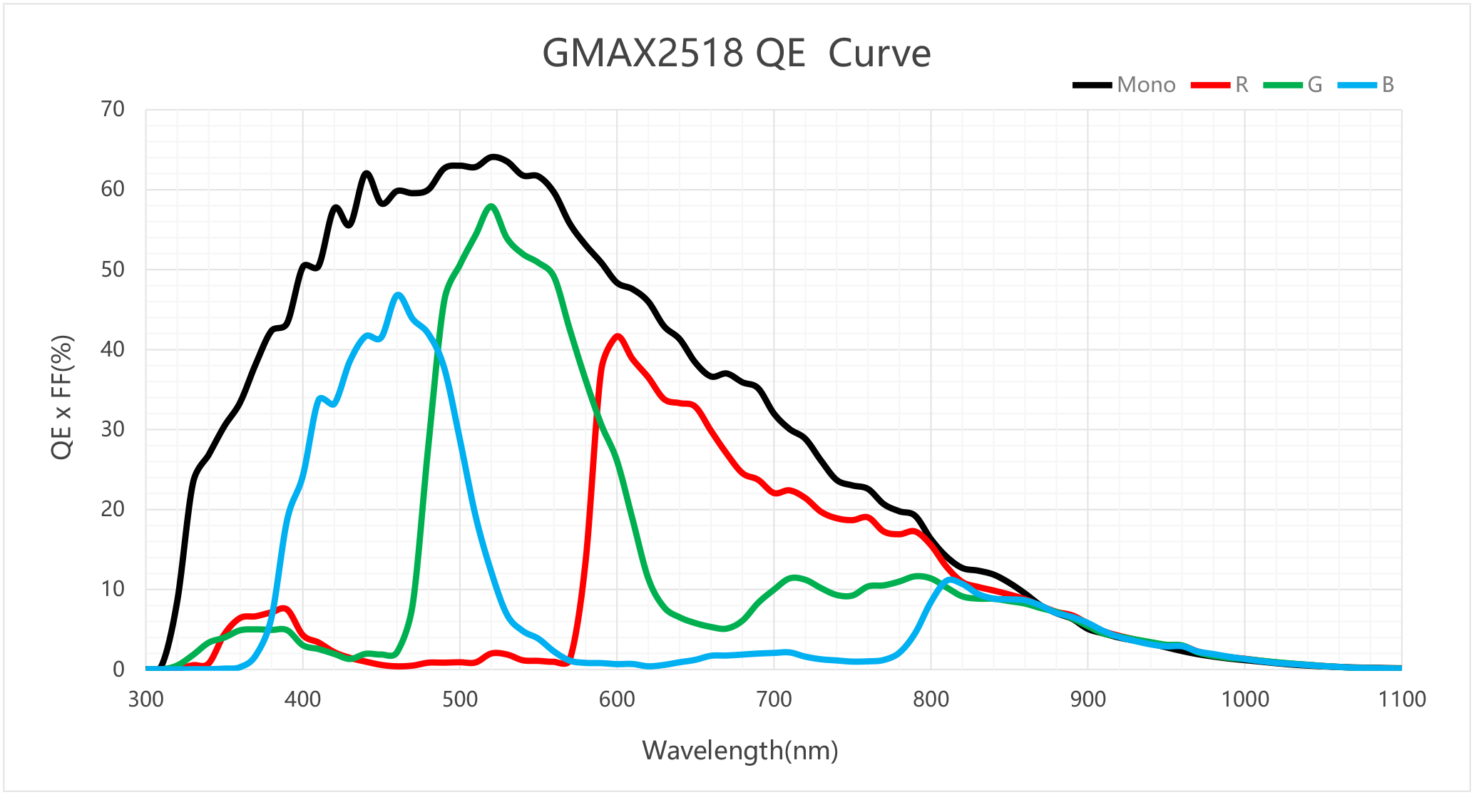
As you can see, the sensor's sensitivity peaks at a wavelength of 520 nm, which is green — and this is precisely the type of laser we used in our system. An additional argument is that 520 nm performs well in various operating conditions, making it, in our opinion, the optimal choice.
Laser diode power
Laser power is usually given in milliwatts (mW) , and this is no coincidence — just 5 mW is enough to cause permanent eye damage. Lasers with power above 1 W certainly exist and are sometimes necessary, but they require significantly greater caution during operation.
Choosing the power is one of the more difficult decisions in the entire system, as many variables influence it, including:
- the width of the surface the laser line needs to cover,
- the lens aperture setting,
- the size of the camera sensor,
- the sensor exposure time,
- the distance of the camera from the laser line,
- external lighting conditions.
As you can see, there are many variables, and it's difficult to calculate a "magic" power value beforehand. In practice, the trial-and-error method works best — we start with lower power and gradually increase it until we achieve satisfactory line quality.
It's important to remember safety. The more powerful the laser, the greater the risk to people working nearby. For lasers above 1 W, the standard is to enclose them in a sealed, impenetrable enclosure without any human access. If, however, the system is to operate where people have access to it, it's advisable to stick to power levels below 1 W.
What's next?
With this post, we've covered the three key components of a vision system for surface inspection: the camera, optics, and laser. In subsequent posts, we will show how these elements combine into a functional whole — we will move on to the construction of a laboratory setup and demonstrate how to build your own production line for testing.